00 Sitka / Hawaiian Koa falcate steel string.

Show us how your current project is progressing
John Parchem
Posts: 2725
Joined: Fri Dec 23, 2011 8:33 pm
Location: Seattle
Contact:

Re: 00 Sitka / Hawaiian Koa falcate steel string.

Post by John Parchem » Sat Jun 15, 2024 3:38 pm

I finally pulled the trigger on a small CNC machine, a Genmitsu PROVerXL 4030 V2. I had always feared the CAD part of it so I tried the free trial of vcarve and drew out a Gore style bridge and simulated the tool paths.

Image

Image

Using just 2.5D there is some limits in terms of 3D profiles. In this case sloping the block top to bottom. Instead I etch some lines and finish up by hand. To test the process I cut out a bridge in poplar practicing a bit before I carve the rosewood.

Image

Image

Image

Image

Kevin in California
Posts: 2770
Joined: Mon Dec 19, 2011 4:19 pm

Re: 00 Sitka / Hawaiian Koa falcate steel string.

Post by Kevin in California » Sat Jun 15, 2024 11:51 pm

That's very cool. Your machine is much bigger/better than mine.
I should really spend some time learning to use mine to make parts like that.
I have V Carve but haven't dug into it yet.
Looks like you caught on to it pretty quick.

John Parchem
Posts: 2725
Joined: Fri Dec 23, 2011 8:33 pm
Location: Seattle
Contact:

Re: 00 Sitka / Hawaiian Koa falcate steel string.

Post by John Parchem » Fri Jun 28, 2024 12:28 am

Little by little I still been gather and fabricating what I need to build the guitar.

Image

I using epoxy I laminated the previously bent strips and split them to form the two sets of falcate braces.

Image

Image

Image

Image

I finally did some real routes with the CNC. I designed a three ring rosette as a nod to a Martin 00.

Image

Still new to CAD I ran a test run on a square of spruce I had from a previously ruined top.

Image

With the CNC running I joined a couple scraps of Koa to use as a wood ring.

Image

Image

Image

Image

Cut out the ring

Image

Test the test run.

Image

Run the toolpath on the real top and make the rosette.

Image

I used some seal lac and alcohol to seal the channels.

Image

I installed all of the rings and flooded with ultra thin CA.

Image

Image

I leveled the rings I will still need to clean it up a bit.

Image

John Parchem
Posts: 2725
Joined: Fri Dec 23, 2011 8:33 pm
Location: Seattle
Contact:

Re: 00 Sitka / Hawaiian Koa falcate steel string.

Post by John Parchem » Sat Jul 06, 2024 3:38 pm

Little by little I am making progress. A bunch of my work (play) is hidden while I play in the CAD software. I worked out the straight string contemporary headstock that incorporates a client supplied inlay. I will use my cnc to cutout the headstock when the time comes.

Image

I used my Fox bender to bend a set of profiled sides. No issues; I thicknessed the sides to .080" and bent them at around 285F. I sprayed the cutaway side with Supersoft II and let it sit wrapped for about 8 hours.

Image

Image

I am using the CNC router to make templates for the build. In the picture below I made a bridge hole template where the leading edge of the template is the leading edge of the saddle. The falcate braced top need the bridge peg holes drilled before bracing. The template will really help place the holes relative to the saddle location.

Image

On the fun side, I have a vectorized version of my logo. I etched it with my CNC router, filled it with black CA and sanded it back.

Image

Kevin in California
Posts: 2770
Joined: Mon Dec 19, 2011 4:19 pm

Re: 00 Sitka / Hawaiian Koa falcate steel string.

Post by Kevin in California » Sat Jul 06, 2024 10:08 pm

Very cool. You're having fun with the CNC.

John Parchem
Posts: 2725
Joined: Fri Dec 23, 2011 8:33 pm
Location: Seattle
Contact:

Re: 00 Sitka / Hawaiian Koa falcate steel string.

Post by John Parchem » Wed Jul 10, 2024 12:40 am

With the sides bent I used titebond to glue on the tail and neck block. The tail block is straight forward with the sides trimmed to size on the bandsaw and the belt sander.

Image

Image

I have always struggled clamping clamping the heel block to the cutaway sides. This time it finally hit me that there is no need to glue both sides on at once.
So I first glued the cutaway aligned and glued on the cutaway side.

Image

Image

After a couple of hours I glued on the non cutaway side.

Image

Image

Before profiling the sides I used the square top side to evenly place the sides in the molds and then marking a couple of lines to help me realign the sides in the mold after the top and bottom are profiled.

Image

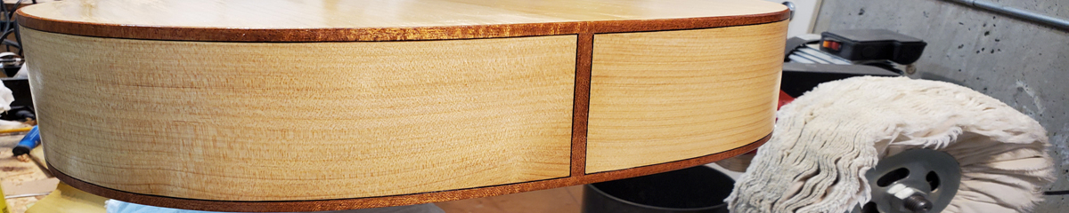
Starting on the back sides I used a plane to remove most of the excess. The sides were profiled but tall. I marked the sides down a few millimeters and used a plane to take them down to the lines.

Image

Then I used a 10' radius board to clean up the sides to the 10' profiles.

Image

Leaving the rims on the 10' radius board I used a 32' radius board for the top profile.

Image

In the picture above notice that I do most of the sanding on the lower bout. I lower the lower bout to create the correct angle for the neck angle. Most builders profiled the entire top and work on the upper bout to create the correct angle. I instead get most of the angle by dropping the lower bout.

I any case I profile the rims until an unbrace top held on the rims show that I have the right angle.

First is too low needs more work

Image

After a bit more work the 3 mm bit shows me I am close.

Image

Once the top is braced I play with the profile more to make the fit perfect.

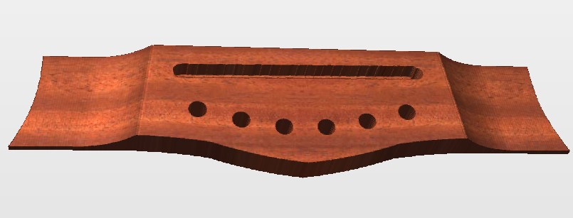
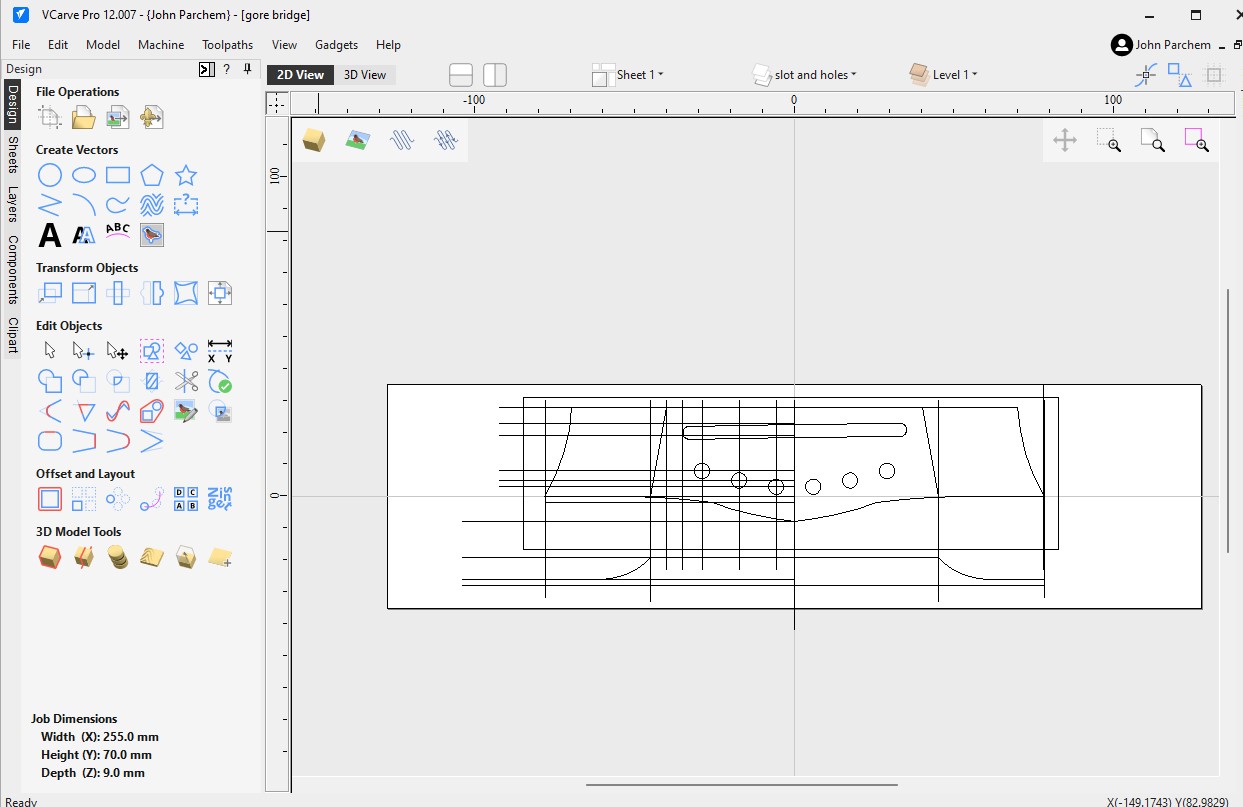
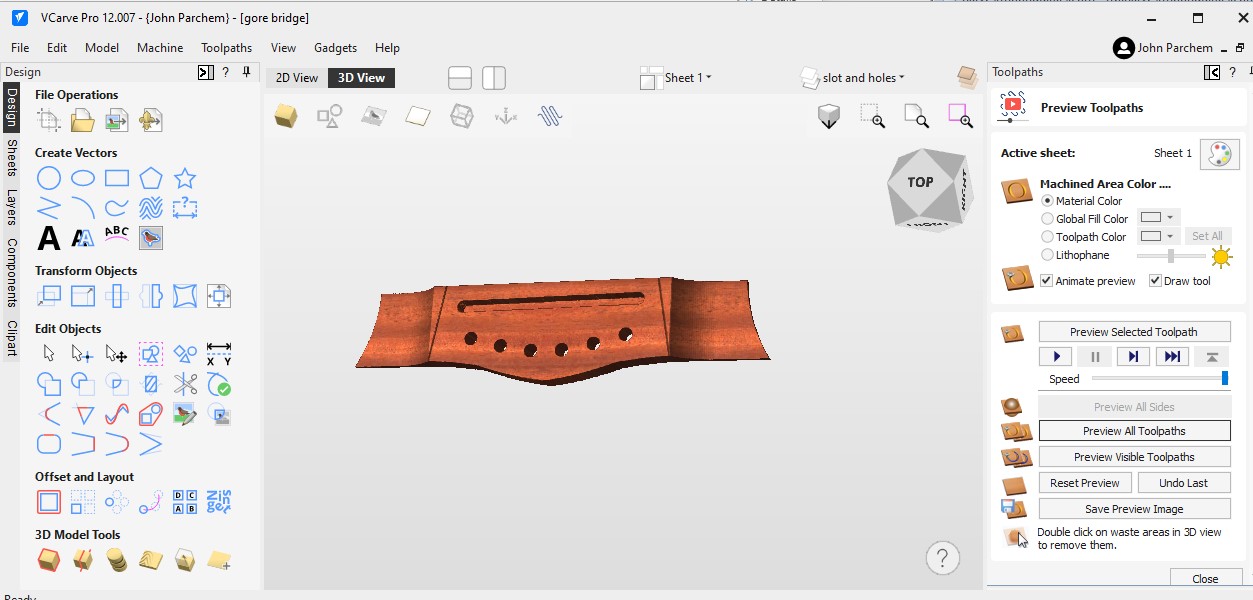
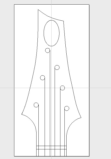
On the CAD front I figured out how to profile the wings with the trapezoid block shape.

Image

John Parchem
Posts: 2725
Joined: Fri Dec 23, 2011 8:33 pm
Location: Seattle
Contact:

Re: 00 Sitka / Hawaiian Koa falcate steel string.

Post by John Parchem » Sun Jul 14, 2024 2:42 pm

Sure I am a bit distracted playing with my CNC but I am doing some useful work. The bridge pins need to be located and drilled early on a falcate braced steel string acoustic. The primary falcate braces need to go between bridge pins (I suppose I could go pin less!). So to make the placement easy I made a hole guide where the leading edge of the guide is the leading edge of the saddle at the high E location. This guide makes it really easy to locate, center and square the hole guide.

Image

The drilled holes are used to index the, in this case a hard maple, bridge plate also cut with the CNC. The bridge plate is 1.5 mm with a laminated CF weave between it and the top. While Gore's process is to put the CF tow for the primary falcate braces down at the same time as the bridge plate I have found it is too stressful to do the plate and the falcate braces at the same time. So I installed the plate by itself. When I epoxy the falcate braces down I will run the CF tow over the plate under the falcate brace.

Image

Not to waste the epoxy I mixed I made a laminated bridge blank, from top: 3 mm Brz rosewood, CF weave, 8 mm Brz rosewood.

Image

Image

Bridge plate epoxied on top

Image

While waiting for the epoxy to cure I carved a test bridge from a rosewood blank I had. I will use this for a non falcate guitar in the future.

Image

Image

Image

Happy with the bridge I carved one with the laminated blank

Image

Image

Moving back to the top I put in the rebates for the bridge plate in the primary falcate braces. I used a razor saw for depth and just carefully used a chisel clear the rebate.

Image

Image

Image

Finally today I epoxied on the falcate braces. Sorry no in process pictures as I always have epoxy on my fingers. So a picture getting ready. Mise en place!

Image

Image

Post Reply